Design and Build an ESP8266 Based IoT Controller Part 1 Circuit Diagram
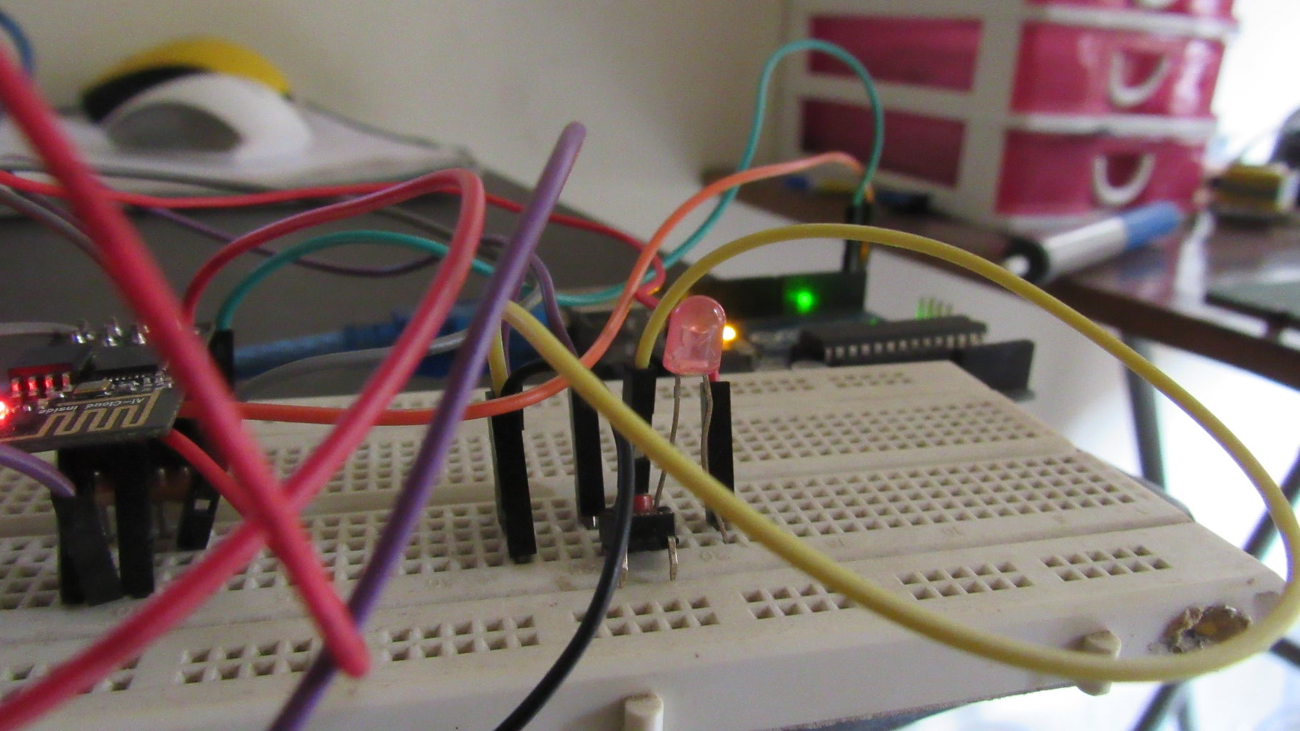
Design and Build an ESP8266 Based IoT Controller Part 1 Circuit Diagram During the article, I have shown all the steps to make this smart home system. This ESP8266 NodeMCU control smart relay has the following features: Connect multiple NodeMCUs with the same Blynk account. Control home appliances with WiFi (Blynk App) Control home appliances with manual switches. Monitor real-time feedback in the Blynk App.
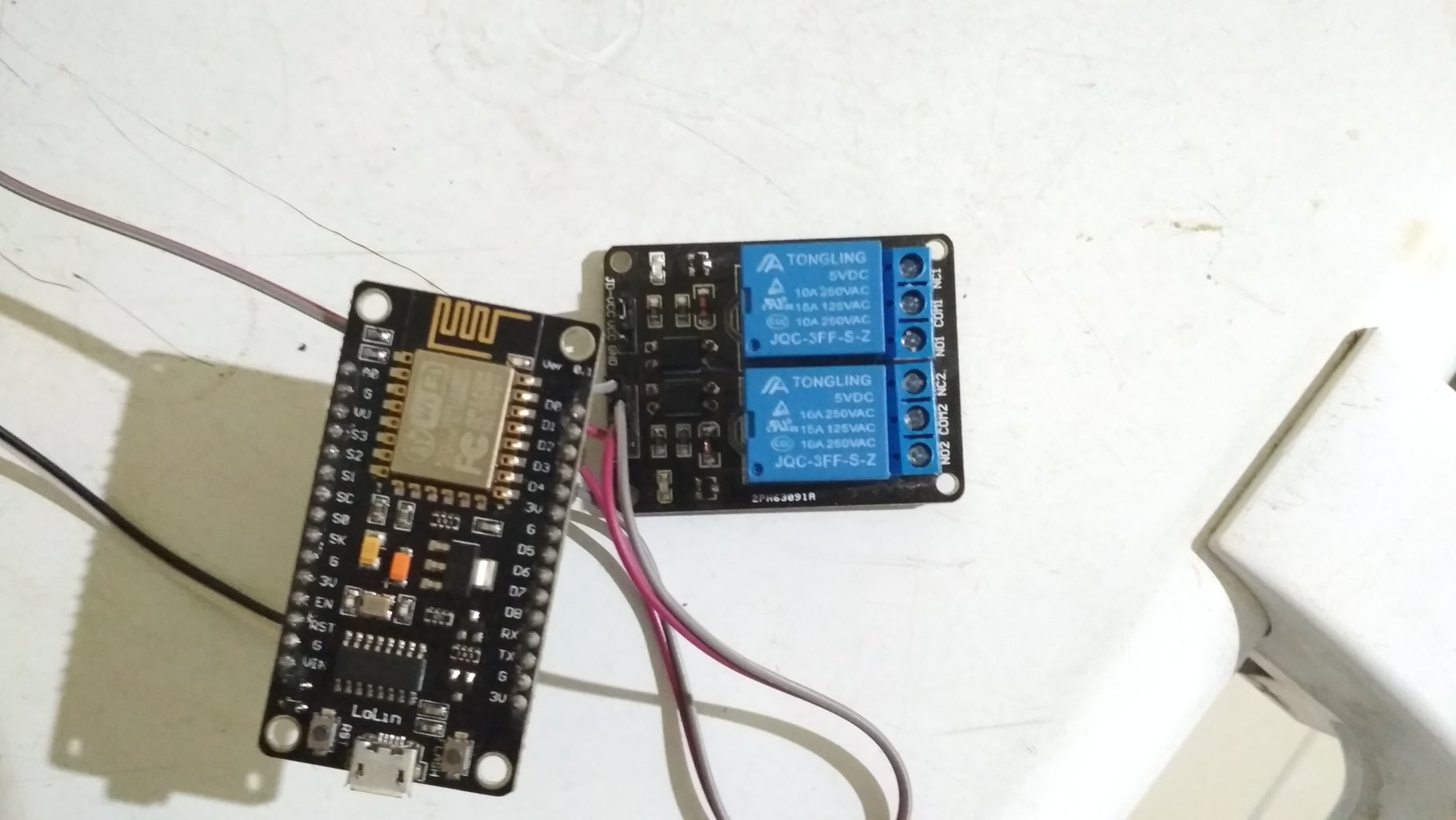
This NodeMCU ESP8266 control smart relay has the following features: 1. Control home appliances through the internet. 2. Control home appliances manually with pushbuttons. 3. Monitor real-time feedback on the smartphone. So, you can easily make this home automation project at home just by using an ESP8266 NodeMCU and relay module.
intercom: ESPHome firmware config for ESP8266 ... Circuit Diagram
Description: ESP8266 Arduino project smart intercom ESP-01, The best Arduino project. We made a smart intercom using Esp8266 with Arduino. By using the Internet of Things IOT, you can access the intercom in your home from anywhere with the Internet. Control your Arduino project with the mobile app. as well as from all over the world. Mobile App Control home appliances with WiFi (Blynk IoT App). Control home appliances with Blynk web dashboard. Control home appliances with manual switches or push buttons. Monitor real-time feedback in the Blynk IoT App. So, you can easily make this home automation project at home just by using a NodeMCU and relay module.
But before that, you can check some of our Home Automation Projects made using ESP8266 or ESP32: 1. Home Automation using NodeMCU & Alexa 2. Home Automation with Arduino IoT Cloud using ESP32 3. Home Automation using ESP8266 WebServer 4. Home Automation using Blynk & NodeMCU 5. Home Automation using Google Firebase & NodeMCU 6.
DIY Examples — ESPHome Circuit Diagram
Make IoT-based Smart Home Automation using Multiple NodeMCU ESP8266 network to control all the home appliances from the pushbuttons & Blynk. Find this and other hardware projects on Hackster.io. Smart Home With Multiple NodeMCU ESP8266 Network With Blynk. Create buttons with V1,V2, V3, V4, V5, V6, V7, ESP8266 Arduino project smart intercom ESP-01, The best Arduino project. We made a smart intercom using Esp8266 with Arduino. By using the..