Mini Adjustable Voltage Regulator 5 Steps with Pictures Circuit Diagram
Mini Adjustable Voltage Regulator 5 Steps with Pictures Circuit Diagram Basic Uses of the LM317 Voltage Regulator. From the above, we have learned about pinout and features. Now let's get on learning about the basic regulator circuit. The typical circuit diagram. This is a USB 5V to 1.5V step-down converter circuit using the LM317 voltage regulator. When we use a cheap MP3 Player which uses only one 1.5V AA
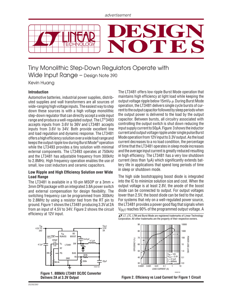
The voltage rating of the output capacitor should be about 30% greater than the maximum input supply voltage. Even for a step-down regulator with fixed output voltage, in the event of failure of regulation the output voltage may rise to the input voltage. Consequently, to avoid catastrophic failure of the output capacitor it should be rated to

Simple Buck Converter Circuits using Transistors Circuit Diagram
Input voltage of the LM317 is 4.25 - 40 V. Output voltage of the LM317 is 1.25 - 37 V. Voltage drop down is about 2 V, meaning that we need at least 5.3 V to get 3.3 V. The maximum current rating is 1.5 A, it's highly recommended to use a Heat Sink with the LM317. The MAX639 integrated step-down converter is a highly efficient and compact solution for voltage regulation in electronic circuits. Its ability to minimize heat generation and simplify the design process makes it ideal for applications where space and cooling are limited, offering reliable performance across a range of devices and projects.
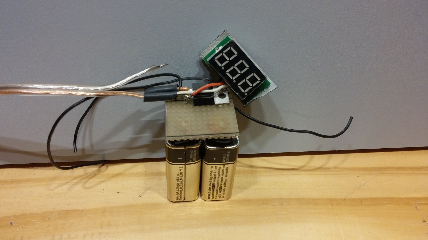
How to Build. Step#1: Take 20 mm by 20 mm general purpose strip board. Spep#2: Clean the copper side with a sand paper. Step#3: Take the resistors and the diodes and bend their leads leaving 1 mm distance between their body and the leads. Step#4: Insert the resistors into the PCB and solder them. Cut the excess lead lengths.

LM317 Adjustable Voltage Regulator : 6 Steps Circuit Diagram
In this instructable, you will learn how to make a DC to DC voltage Step-Up booster circuit. Input= 32 v and Output= 2 v . Items Needed: - 2 power transistors CTC 1351 - 2 resistors 1 kilo ohm - 1 transformer Center tap - 1 Single phase bridge rectifier - 1 power source 32v - 1 multi-meter - 1 universal board . Buy Cheap PCBs Here: www.pcbway.com The Tail Servo Step-Down Voltage Regulator is ideally designed to step-down a voltage source of 6 volts that is outputted from any external BEC (battery eliminator circuit) down to 5.2 volts. This allows an external 6 volt BEC to be used with Futaba 9241, 9251, 9253, 9254, 9255, and 9256 servo models, as well as other digital servos that are